


Geomechanics is used to analyse drilling risks; pre-drill, during drilling and post-drilling. By integrating technical data from geology, petrophyscis and reservoir engineering data models in 1D, 3D and 4D can be developed that are useful to drilling. Well bore stability is affected by rock stresses that can cause a collapse.
Safe well trajectories can be identified in a 3D geomechanical field and completions can be designed that will withstand production-induced compaction.
At the reservoir level, geomechanical models can be used to analysis pore pressure, fault and top seal integrity, compaction, subsidence and the effects of injection / depletion on cap rock behaviour.

Wellbore stability analysis is a critical aspect of drilling operations in the oil and gas industry, as it ensures the integrity of the wellbore during and after drilling. The analysis involves understanding the mechanical properties of the rock formations encountered, the in-situ stresses, and the impact of drilling activities on these factors. A stable wellbore prevents problems such as wellbore collapse, stuck pipe, lost circulation, and formation damage, which can lead to costly delays or even the loss of the well.
Importance of Wellbore Stability Analysis
1. Preventing Wellbore Collapse:
– Ensuring that the wellbore walls remain intact during drilling is crucial to avoid collapse. If the wellbore collapses, it can trap the drilling string, leading to non-productive time (NPT) and potential abandonment of the well.
2. Avoiding Stuck Pipe:
– Stuck pipe occurs when the drill string becomes immovable within the wellbore, often due to wellbore instability. Proper analysis helps in designing drilling parameters that minimize the risk of the drill string getting stuck.
3. Mitigating Lost Circulation:
– Lost circulation happens when drilling fluid escapes into the formation instead of returning to the surface. This can be caused by fractures or highly permeable zones, which can be predicted and managed through wellbore stability analysis.
4. Reducing Drilling Costs:
– A stable wellbore reduces the risk of complications that can increase drilling time and costs. By predicting and mitigating instability issues, operators can avoid expensive remedial actions.
5. Ensuring Well Integrity:
– Wellbore stability is also crucial for the long-term integrity of the well, particularly in maintaining zonal isolation and preventing casing deformation.
Key Factors in Wellbore Stability Analysis
1. In-Situ Stresses:
– Vertical Stress (σv): This is the overburden pressure, which is the weight of the rock column above the point of interest. It generally increases with depth.
– Horizontal Stresses (σhmax and σhmin): These are the maximum and minimum horizontal stresses in the formation. The difference between these stresses can create anisotropy that affects wellbore stability.
2. Pore Pressure:
– Formation Pressure: This is the pressure within the pore spaces of the rock. If the pore pressure is too high (overpressure), it can lead to wellbore instability by reducing the effective stress that holds the formation together.
– Mud Weight (Mud Pressure): The pressure exerted by the drilling fluid helps counterbalance the formation pressure. The mud weight needs to be carefully controlled to maintain wellbore stability.
3. Rock Mechanical Properties:
– Unconfined Compressive Strength (UCS): This measures the strength of the rock when it is unconfined. It is a key parameter in determining how the rock will behave under drilling conditions.
– Young’s Modulus: This measures the rock’s stiffness or elasticity. A higher Young’s modulus indicates a stiffer rock, which may be more prone to fracturing.
– Poisson’s Ratio: This measures the rock’s ability to deform in directions perpendicular to the applied stress. It influences the stress distribution around the wellbore.
4. Wellbore Orientation:
– Inclination and Azimuth: The angle and direction of the wellbore relative to the in-situ stress field can greatly influence stability. Certain orientations may exacerbate stress concentrations, leading to instability.
– Deviated Wells: For deviated or horizontal wells, the wellbore stability analysis becomes more complex due to the changing stress conditions along the well path.
5. Time-Dependent Effects:
– Creep: Some formations, particularly salt, can slowly deform over time, potentially causing the wellbore to close in.
– Chemical Interaction: The interaction between the drilling fluid and the formation can lead to changes in rock strength or induce swelling, affecting stability.
Wellbore Stability Analysis Workflow
1. Data Collection:
– Geomechanical Data: This includes laboratory tests on core samples to determine rock mechanical properties, well logs (such as sonic, density, and image logs), and in-situ stress measurements.
– Pore Pressure Estimation: Pore pressure can be estimated from well logs, drilling data, and regional pressure trends.
– Drilling History: Information about previous wells, including any instability issues encountered, is valuable for understanding the subsurface conditions.
2. Stress Analysis:
– In-Situ Stress Estimation: The magnitude and orientation of in-situ stresses are determined using well logs, leak-off tests (LOT), extended leak-off tests (XLOT), and other methods.
– Stress Modeling: A 3D stress model is often created to visualize how stresses vary along the wellbore path, particularly in deviated wells.
3. Rock Failure Criteria:
– Mohr-Coulomb Criterion: This criterion is commonly used to evaluate shear failure, which can lead to wellbore collapse.
– Mogi-Coulomb and Drucker-Prager Criteria: These criteria account for the influence of intermediate stress, providing a more accurate prediction of failure in certain conditions.
– Tensile Failure: If the mud weight is too high, it can induce tensile failure in the formation, leading to fracturing and lost circulation.
4. Mud Weight Window Determination:
– Lower Bound: The minimum mud weight required to prevent wellbore collapse.
– Upper Bound: The maximum mud weight that can be used without fracturing the formation.
– Operational Window: The safe range of mud weights within which the well can be drilled without encountering significant stability issues.
5. Numerical Modeling:
– Finite Element Analysis (FEA): FEA is used to simulate the stress distribution around the wellbore and predict zones of potential failure.
– Discrete Element Modeling (DEM): DEM is useful for simulating rock behavior at the granular level, particularly in fractured or faulted formations.
6. Mitigation Strategies:
– Mud Program Design: Based on the stability analysis, a mud program is designed to maintain the wellbore within the safe operational window.
– Wellbore Strengthening: Techniques such as the use of bridging agents in the drilling fluid can help reinforce the wellbore and prevent collapse.
– Casing Design: Proper casing and cementing programs are essential to maintain wellbore stability, particularly in weak or fractured zones.
7. Real-Time Monitoring:
– Measurement While Drilling (MWD): Real-time data from MWD tools, including wellbore pressure, inclination, and azimuth, is used to monitor wellbore conditions.
– Geomechanical Monitoring: Continuous monitoring of wellbore stability during drilling allows for quick adjustments to drilling parameters if instability is detected.
Challenges in Wellbore Stability Analysis
1. Uncertainty in Data:
– Accurate wellbore stability analysis relies on precise geomechanical data, which can be challenging to obtain. Variations in rock properties, stress conditions, and pore pressures introduce uncertainty into the analysis.
2. Complex Geological Settings:
– In regions with complex geology, such as those with highly anisotropic stress fields, faulted formations, or salt tectonics, wellbore stability analysis becomes more difficult, requiring advanced modeling techniques.
3. Dynamic Drilling Conditions:
– The conditions in the wellbore can change dynamically during drilling, with pressure and stress variations caused by drilling activities, mud weight changes, and formation fluid influx. These dynamic conditions must be continuously managed to maintain stability.
4. Time-Dependent Rock Behavior:
– Time-dependent effects such as creep, particularly in salt formations, and chemical interactions between the drilling fluid and the formation can complicate the prediction of wellbore stability.
Conclusion
Wellbore stability analysis is essential for the successful and cost-effective drilling of oil and gas wells. By understanding the in-situ stresses, rock mechanical properties, and drilling conditions, engineers can predict and mitigate potential stability issues, ensuring the integrity of the wellbore throughout its lifecycle. Advanced modeling techniques, real-time monitoring, and well-designed mitigation strategies are key components of effective wellbore stability management, particularly in complex and challenging geological environments.
Rock failure analysis is a crucial aspect of geomechanics and plays a significant role in various fields, including petroleum engineering, mining, civil engineering, and geological studies. This analysis focuses on understanding the conditions under which rocks will fail, the mechanisms of failure, and the implications for engineering and geological applications. Rock failure can occur due to various factors such as stress, pressure, temperature, chemical reactions, and mechanical loading, and it is essential to predict and manage these failures to ensure safety, stability, and efficiency in engineering projects.
Importance of Rock Failure Analysis
1. Safety in Engineering Projects:
– In infrastructure projects like tunnels, dams, and buildings, rock failure can lead to catastrophic consequences. Understanding rock failure helps in designing structures that can withstand geological conditions.
2. Oil and Gas Exploration:
– In petroleum engineering, rock failure analysis is essential for drilling, hydraulic fracturing, and reservoir management. It helps in predicting wellbore stability, fracture propagation, and optimizing extraction techniques.
3. Mining Operations:
– Rock failure analysis is critical in mining for designing stable underground excavations and preventing collapses. It also aids in optimizing ore recovery and minimizing environmental impacts.
4. Natural Hazard Assessment:
– Understanding the failure mechanisms of rocks is essential for assessing and mitigating natural hazards such as landslides, earthquakes, and volcanic eruptions.
Key Concepts in Rock Failure Analysis
1. Stress and Strain:
– Stress: The force applied per unit area within a rock. It can be compressive, tensile, or shear, depending on the direction of the applied force.
– Strain: The deformation or displacement experienced by the rock in response to stress. It can be elastic (reversible) or plastic (permanent).
2. Failure Criteria:
– Mohr-Coulomb Criterion: A widely used failure criterion that defines the conditions under which shear failure occurs. It is based on the relationship between shear stress, normal stress, and the material’s internal friction angle and cohesion.
– Hoek-Brown Criterion: A failure criterion specifically developed for rock masses, considering the rock’s inherent properties and the effects of fractures and discontinuities.
– Griffith Criterion: This criterion is based on the theory of brittle fracture and is used to predict the tensile failure of rocks.
3. Modes of Rock Failure:
– Tensile Failure: Occurs when the tensile stress exceeds the tensile strength of the rock, leading to crack initiation and propagation. Tensile failure is often associated with the formation of fractures or joints.
– Compressive Failure: Happens when compressive stress exceeds the rock’s compressive strength, leading to crushing or compaction. This type of failure is common in deep, high-pressure environments.
– Shear Failure: Occurs when shear stress overcomes the rock’s shear strength, resulting in sliding along a plane. Shear failure is typical along faults, fractures, and bedding planes.
4. Rock Mechanical Properties:
– Unconfined Compressive Strength (UCS): A measure of the rock’s ability to withstand compressive stress without lateral confinement. It is a key parameter in rock failure analysis.
– Young’s Modulus: Describes the rock’s stiffness or elasticity, influencing how it deforms under stress.
– Poisson’s Ratio: The ratio of lateral strain to axial strain, providing insight into the rock’s deformation characteristics.
– Tensile Strength: The maximum stress a rock can withstand in tension before failure.
5. Fracture Mechanics:
– Fracture Toughness: The rock’s resistance to fracture propagation. It is a critical parameter in predicting the growth of fractures under stress.
– Crack Initiation and Propagation: The process by which micro-cracks form and grow, leading to macroscopic failure. This process is influenced by stress concentration, rock properties, and environmental conditions.
Methods of Rock Failure Analysis
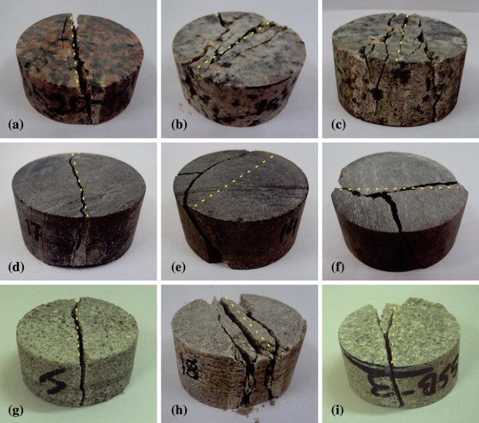
1. Laboratory Testing:
– Triaxial Compression Test: This test subjects a rock sample to controlled axial and confining pressures to simulate in-situ stress conditions. It provides valuable data on the rock’s compressive strength, failure envelope, and deformation characteristics.
– Brazilian Tensile Test: A method to determine the tensile strength of rocks by applying diametral compression to a cylindrical rock specimen.
– Direct Shear Test: Measures the shear strength of rock specimens by applying a shear force along a predetermined plane, often used for rock joints and discontinuities.
2. Numerical Modeling:
– Finite Element Method (FEM): A numerical technique used to simulate the stress distribution and deformation in rocks under various loading conditions. FEM models can predict failure patterns and assess the stability of rock structures.
– Discrete Element Method (DEM): This method models rocks as an assembly of discrete particles, allowing for the simulation of rock behavior, including fracture initiation and propagation.
– Boundary Element Method (BEM): Used to model stress and displacement in rock masses, particularly useful for analyzing problems involving fractures and faults.
3. Field Observations:
– In-Situ Stress Measurements: Techniques like hydraulic fracturing, overcoring, and borehole breakouts are used to measure the in-situ stress state, providing critical data for rock failure analysis.
– Geological Mapping: Mapping faults, fractures, and other discontinuities in the field helps in understanding the structural controls on rock failure.
– Seismic Monitoring: Seismic data can be used to detect microseismic events associated with rock failure, particularly in hydraulic fracturing and mining operations.
4. Analytical Methods:
– Stress Analysis: Analytical solutions, such as those based on elasticity or plasticity theory, can be used to calculate the stress distribution around excavations, boreholes, and other rock structures.
– Failure Envelope Construction: By plotting stress conditions on a Mohr’s circle or other diagrams, engineers can assess the likelihood of rock failure under different loading scenarios.
Applications of Rock Failure Analysis
1. Wellbore Stability:
– Preventing Collapse: Rock failure analysis helps in designing drilling parameters and selecting appropriate mud weights to prevent wellbore collapse.
– Fracture Control: In hydraulic fracturing, understanding rock failure is crucial for predicting fracture propagation and optimizing fracture networks for enhanced hydrocarbon recovery.
2. Underground Excavations:
– Tunnel Design: Rock failure analysis is essential in designing safe and stable tunnels, particularly in complex geological settings.
– Mining Operations: In underground mining, rock failure analysis guides the design of stable stopes, pillars, and shafts to prevent collapses and optimize ore recovery.
3. Slope Stability:
– Landslide Prevention: Analyzing the conditions leading to rock failure on slopes helps in designing preventive measures for landslides and other slope-related hazards.
– Retaining Wall Design: Rock failure analysis aids in the design of retaining walls and other support structures for slopes and embankments.
4. Reservoir Engineering:
– Fracture Management: In reservoir engineering, understanding rock failure is critical for managing fractures, which can impact fluid flow and reservoir performance.
– Caprock Integrity: Ensuring the integrity of caprock in oil and gas reservoirs or CO2 storage sites is vital to prevent leakage and maintain reservoir pressure.
Challenges in Rock Failure Analysis
1. Complex Geological Conditions:
– Heterogeneous and anisotropic rock formations present challenges in accurately predicting failure. Discontinuities, such as faults and fractures, add complexity to the analysis.
2. Data Limitations:
– Obtaining accurate geomechanical data, particularly in-situ stress measurements and rock mechanical properties, can be difficult and expensive. Data scarcity can lead to uncertainties in failure predictions.
3. Non-Linear Behavior:
– Rocks often exhibit non-linear behavior, particularly under high-stress conditions or when approaching failure. Capturing this behavior accurately in models is challenging.
4. Scale Effects:
– Rock behavior can vary significantly with scale, from the laboratory sample to the field scale. Laboratory tests may not fully capture the behavior of large rock masses in the field.
5. Time-Dependent Failure:
– Some rocks, such as shale or salt, exhibit time-dependent deformation (creep), which complicates the prediction of failure over long periods.
Conclusion
Rock failure analysis is a vital aspect of geomechanics that informs the design and management of engineering projects in various industries. By understanding the conditions and mechanisms of rock failure, engineers can predict and mitigate risks, ensuring the safety and stability of structures and operations. The integration of laboratory testing, numerical modeling, field observations, and analytical methods allows for a comprehensive approach to rock failure analysis, addressing the challenges posed by complex geological conditions and data limitations. As technology and methodologies advance, rock failure analysis will continue to play a crucial role in optimizing engineering designs and managing geological hazards.
Fault seal integrity is a critical concept in subsurface geology, particularly in the fields of petroleum exploration, carbon capture and storage (CCS), and groundwater management. It refers to the ability of a fault to act as a barrier to fluid flow, effectively trapping hydrocarbons, CO₂, or other fluids within a reservoir. A thorough understanding of fault seal integrity is essential for assessing the viability of subsurface resources and preventing unwanted fluid migration, which could lead to environmental hazards or the failure of resource development projects.
Importance of Fault Seal Integrity
1. Hydrocarbon Trapping:
– Faults that maintain seal integrity can trap hydrocarbons within a reservoir, forming significant oil and gas accumulations. A failure in fault seal integrity could lead to hydrocarbon leakage, reducing the size and economic value of the reservoir.
2. Carbon Capture and Storage (CCS):
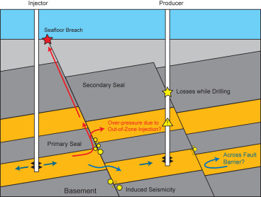
– In CCS projects, the long-term storage of CO₂ in subsurface reservoirs depends on the ability of faults to maintain their seal integrity. Breaches in fault seals could lead to CO₂ leakage, undermining the effectiveness of the storage site and posing environmental risks.
3. Groundwater Protection:
– Fault seal integrity is also critical in preventing the contamination of freshwater aquifers by hydrocarbons, saline water, or other subsurface fluids. Understanding fault behavior helps in designing strategies to protect groundwater resources.
4. Geothermal Energy:
– In geothermal systems, faults can act as conduits for fluid flow or as barriers that compartmentalize reservoirs. The integrity of these seals affects the efficiency and sustainability of geothermal energy extraction.
Factors Influencing Fault Seal Integrity
1. Lithological Juxtaposition:
– Juxtaposition of Permeable and Impermeable Rocks: Faults can create seals when they juxtapose impermeable rock units (e.g., shale) against permeable reservoirs (e.g., sandstone). This can prevent fluids from migrating across the fault.
– Reservoir Sandstone Against Shale: If the fault offsets a permeable sandstone against a sealing shale, the shale can act as a barrier, maintaining the fault seal.
2. Fault Zone Properties:
– Shale Gouge Ratio (SGR): The SGR is a key parameter used to estimate the sealing potential of a fault. It represents the proportion of shale (or other clay-rich material) that has been smeared along the fault surface. Higher SGR values typically indicate better sealing capacity.
– Clay Smear Potential: The extent to which clay-rich layers are smeared along the fault plane can enhance the fault’s sealing ability. The continuity and thickness of these clay smears are critical for maintaining a fault seal.
– Fault Core Composition: The fault core, consisting of fine-grained material like clay, can act as a seal if it is sufficiently impermeable. The thickness and continuity of this core are important factors.
3. Stress Conditions:
– In-Situ Stress: The state of stress in the subsurface influences whether a fault will act as a seal or a conduit. High normal stress across a fault can enhance sealing by compressing the fault zone materials, while low normal stress might promote fault reactivation and fluid flow.
– Fault Reactivation: Changes in subsurface stress, such as those induced by drilling, production, or tectonic activity, can lead to fault reactivation. Reactivation can compromise seal integrity, leading to fluid migration.
4. Fault Architecture:
– Fault Geometry: The orientation, dip, and shape of a fault influence its sealing behavior. For example, a fault that is favorably oriented relative to the current stress field is less likely to slip and may better maintain its seal.
– Fault Throw: The amount of vertical or lateral displacement (throw) along a fault can determine the juxtaposition of different rock units and thus affect seal integrity.
Methods for Assessing Fault Seal Integrity
1. Geological Modeling:
– 3D Reservoir Models: Building 3D models of the subsurface that incorporate fault geometries, lithologies, and properties allows geoscientists to simulate fluid flow and assess fault seal integrity. These models are used to predict the behavior of faults under various scenarios.
– Fault Seal Analysis Software: Specialized software tools, such as TrapTester and Petrel, are used to perform fault seal analysis. These tools calculate parameters like SGR and help visualize fault behavior in three dimensions.
2. Seismic Interpretation:
– Seismic Data: High-resolution seismic data is crucial for mapping faults, understanding their geometry, and identifying key lithological contacts. Seismic attributes can also provide information about fault zone properties and potential fluid migration pathways.
– Seismic Attribute Analysis: Attributes such as amplitude, coherence, and curvature can be analyzed to infer the presence of fault zones and assess their sealing potential.
3. Well Data:
– Core and Log Data: Core samples and well logs provide direct measurements of rock properties in and around faults. These data are essential for calibrating models and validating fault seal predictions.
– Pressure Data: Pressure measurements across faults can indicate whether a fault is acting as a seal or a conduit. Differences in pressure on either side of a fault can suggest the presence of a sealing fault.
4. Petrophysical Analysis:
– Porosity and Permeability: Understanding the porosity and permeability of fault zone materials helps in assessing their potential to act as a seal. Low-permeability rocks and fault gouges are more likely to maintain fault seal integrity.
– Capillary Pressure: Capillary pressure measurements help determine the sealing capacity of faults by indicating the maximum pressure differential that the fault can sustain without leaking.
5. Geomechanical Modeling:
– Stress Analysis: Geomechanical models simulate the stress conditions around faults and predict the likelihood of fault reactivation. These models help in assessing the stability of fault seals under different loading conditions.
– Fault Slip Potential: By calculating the slip tendency of faults, geoscientists can predict which faults are more likely to slip and potentially lose their sealing integrity.
Challenges in Fault Seal Integrity Analysis
1. Data Uncertainty:
– Subsurface data is often limited or uncertain, particularly in complex geological settings. This uncertainty can make it difficult to accurately predict fault seal behavior.
2. Complex Fault Zones:
– Fault zones can be highly heterogeneous, with complex architectures that are difficult to model accurately. Multiple factors, such as varying lithologies and fault geometries, can interact in unpredictable ways.
3. Scale Effects:
– Fault seal behavior can vary significantly depending on the scale of observation, from microscopic clay smears to large-scale fault zones. Capturing this variability in models is challenging.
4. Dynamic Stress Conditions:
– Stress conditions in the subsurface can change over time due to natural processes (e.g., tectonics) or human activities (e.g., production, injection). These dynamic conditions can affect fault seal integrity unpredictably.
Applications of Fault Seal Integrity
1. Exploration and Production:
– Assessing fault seal integrity is critical in the exploration phase to identify viable hydrocarbon traps. During production, maintaining fault seals ensures that hydrocarbons remain contained within the reservoir.
2. Carbon Capture and Storage:
– Ensuring that faults in a storage site can maintain their seal integrity is essential for the long-term storage of CO₂, preventing leakage and ensuring the success of CCS projects.
3. Geothermal Energy:
– In geothermal reservoirs, understanding fault seal integrity helps in optimizing fluid circulation within the reservoir, ensuring efficient energy extraction, and preventing unwanted seismic activity.
4. Natural Hazard Assessment:
– Fault seal integrity is also relevant in assessing the potential for induced seismicity and other geohazards, particularly in areas with active faulting or human-induced stress changes.
Conclusion
Fault seal integrity is a crucial factor in subsurface resource management, influencing the success of projects in oil and gas exploration, carbon capture, geothermal energy, and environmental protection. By understanding and predicting the conditions under which faults can act as effective seals, geoscientists and engineers can make informed decisions about resource exploration, production, and storage. Despite the challenges in data acquisition and modeling, advances in technology and analytical techniques continue to improve our ability to assess fault seal integrity accurately, ensuring the safe and efficient development of subsurface resources.
Pore pressure analysis is a critical aspect of subsurface geomechanics and plays a vital role in various fields such as petroleum engineering, hydrogeology, geotechnical engineering, and earthquake seismology. Understanding and accurately predicting pore pressure is essential for safe and efficient drilling, reservoir management, and hazard mitigation.
What is Pore Pressure?
Pore pressure, also known as formation pressure, is the pressure exerted by fluids within the pore spaces of a rock or sediment. It is a key parameter that influences the mechanical behavior of the subsurface, affecting the stability of boreholes, the potential for hydrocarbon migration, and the risk of geohazards such as landslides or earthquakes.
Types of Pore Pressure
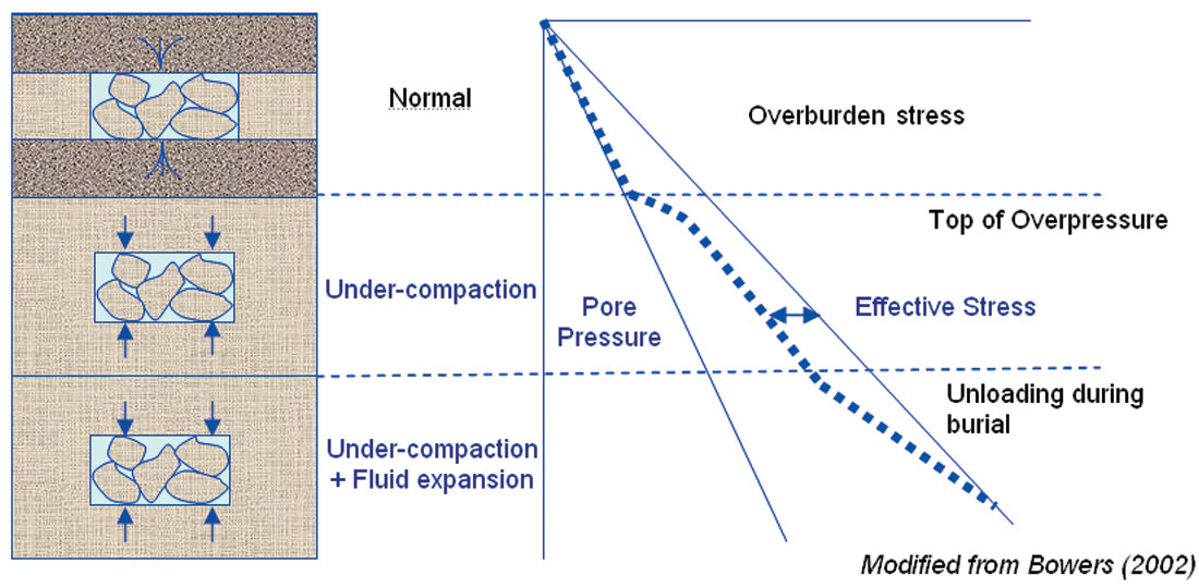
1. Normal Pore Pressure:
– This occurs when the pore pressure is in equilibrium with the hydrostatic pressure, which is the pressure exerted by a column of water extending from the surface to the depth of interest. Normal pore pressure is typically observed in regions where the geological formations are not overpressured.
2. Overpressure (Abnormal Pore Pressure):
– Overpressure occurs when pore pressure exceeds the hydrostatic pressure. This can be caused by various factors such as rapid sedimentation, fluid expansion, or tectonic forces. Overpressure can lead to drilling hazards such as wellbore instability, blowouts, and drilling fluid losses.
3. Underpressure:
– Underpressure is less common and occurs when the pore pressure is lower than the hydrostatic pressure. This condition can arise due to fluid withdrawal, faulting, or tectonic uplift. Underpressure can complicate drilling operations by causing differential sticking of the drill string and difficulties in maintaining well control.
Importance of Pore Pressure Analysis
1. Drilling Safety and Efficiency:
– Accurate prediction of pore pressure is essential for selecting appropriate mud weights and designing well control systems. Overestimation or underestimation of pore pressure can lead to wellbore instability, kicks, blowouts, and other drilling hazards.
2. Reservoir Management:
– Understanding pore pressure distribution within a reservoir helps in optimizing production strategies, enhancing hydrocarbon recovery, and managing reservoir pressure. It also aids in assessing the potential for fluid migration and compartmentalization within the reservoir.
3. Geohazard Mitigation:
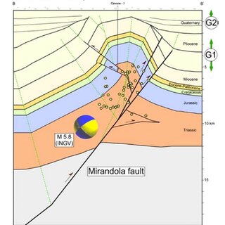
– Pore pressure analysis is crucial for assessing the risk of geohazards such as landslides, subsidence, and induced seismicity. In regions with active faulting, changes in pore pressure can trigger fault reactivation and earthquakes.
4. Wellbore Stability:
– Maintaining wellbore stability is critical during drilling operations. An accurate pore pressure model helps in determining the safe mud weight window, preventing wellbore collapse or fracturing, and ensuring smooth drilling operations.
Factors Affecting Pore Pressure
1. Sedimentation and Compaction:
– Rapid sedimentation can trap fluids within pore spaces, leading to overpressure. As sediments compact under the weight of overlying layers, pore fluids may not have enough time to escape, resulting in abnormal pore pressures.
2. Fluid Expansion:
– Thermal expansion of fluids, hydrocarbon generation, or the influx of fluids from deeper sources can increase pore pressure. For example, the maturation of organic matter into hydrocarbons can generate additional fluids, increasing pore pressure.
3. Tectonic Stress:
– Tectonic forces can alter pore pressure by compressing or extending geological formations. Compressional tectonic regimes often lead to overpressure due to the reduced pore space, while extensional regimes can result in underpressure.
4. Faulting and Fracturing:
– Faults and fractures can act as conduits for fluid flow or barriers, depending on their orientation and properties. Faults that act as seals can trap fluids and increase pore pressure, while open fractures can facilitate fluid migration, potentially lowering pore pressure.
5. Fluid Withdrawal or Injection:
– Human activities such as fluid extraction (e.g., oil, gas, water) or injection (e.g., hydraulic fracturing, CO₂ storage) can alter pore pressure. Fluid withdrawal can lead to underpressure and subsidence, while injection can increase pore pressure and induce seismicity.
Methods for Pore Pressure Analysis
1. Direct Measurements:
– Formation Testing: Tools such as the Repeat Formation Tester (RFT) and Modular Formation Dynamics Tester (MDT) are used to directly measure pore pressure in the formation. These tools provide accurate data but are limited to the points where measurements are taken.
– Drill Stem Test (DST): DST is another method for obtaining direct pore pressure measurements. During a DST, the well is temporarily isolated, and the formation fluids are allowed to flow into the wellbore to measure the pressure response.
2. Indirect Methods (Predictions):
– Seismic Velocity Analysis: Pore pressure can be inferred from seismic velocity data, as the velocity of seismic waves is affected by the pore pressure within the rock. Overpressured formations typically exhibit lower seismic velocities due to higher fluid content and reduced rock stiffness.
– Well Logs: Well logs such as sonic, density, and resistivity logs can be used to predict pore pressure. For instance, the Eaton method utilizes sonic velocity data to estimate pore pressure by comparing it to a normal compaction trend.
– Empirical Methods: Several empirical methods, such as the Eaton or Bowers methods, are used to predict pore pressure from well logs and seismic data. These methods rely on establishing a relationship between rock properties and pore pressure.
3. Numerical Modeling:
– Geomechanical Modeling: Geomechanical models simulate the stress and pressure conditions within the subsurface to predict pore pressure. These models incorporate geological, petrophysical, and mechanical data to provide a more comprehensive understanding of pore pressure distribution.
– 1D, 2D, and 3D Pore Pressure Models: Depending on the complexity of the geological setting, pore pressure models can be constructed in one, two, or three dimensions. 1D models are used for vertical well profiles, while 2D and 3D models provide a more detailed understanding of lateral variations in pore pressure.
4. Analytical Techniques:
– Pressure-While-Drilling (PWD): PWD tools measure the pressure in the wellbore during drilling operations. This real-time data helps in monitoring pore pressure and making adjustments to drilling parameters as needed.
– Mud Weight Analysis: Mud weight is adjusted during drilling to balance the pore pressure. Anomalies in mud weight, such as mud losses or kicks, can indicate changes in pore pressure.
Challenges in Pore Pressure Analysis
1. Data Uncertainty:
– Pore pressure prediction relies on various data sources, such as seismic, well logs, and core samples. However, these data can be uncertain or incomplete, leading to potential inaccuracies in pore pressure models.
2. Complex Geological Settings:
– In areas with complex geology, such as salt diapirs, thrust belts, or highly fractured reservoirs, predicting pore pressure can be challenging. These settings often exhibit significant lateral variations in pore pressure, making accurate modeling difficult.
3. Dynamic Changes:
– Pore pressure is not static and can change over time due to production, injection, or natural processes such as tectonic activity. Monitoring these changes in real-time and adjusting models accordingly is a significant challenge.
4. Scale Effects:
– Pore pressure varies at different scales, from the pore level to the reservoir scale. Capturing this variability in models, especially in heterogeneous reservoirs, is challenging and requires careful integration of data.
Applications of Pore Pressure Analysis
1. Drilling Operations:
– Pore pressure analysis is used to design safe and efficient drilling programs. Accurate pore pressure predictions help in selecting appropriate mud weights, preventing kicks, blowouts, and wellbore instability.
2. Reservoir Management:
– Understanding pore pressure distribution within a reservoir is crucial for optimizing production strategies, managing reservoir pressure, and avoiding issues such as water or gas coning.
3. Geohazard Assessment:
– Pore pressure analysis contributes to assessing the risk of geohazards such as landslides, subsidence, and induced seismicity. It is particularly important in regions with active tectonics or human-induced stress changes.
4. Enhanced Oil Recovery (EOR):
– In EOR operations, managing pore pressure is critical to ensure that the injected fluids, such as water or gas, do not exceed the fracture pressure of the reservoir, leading to unwanted fractures or caprock breaches.
Conclusion
Pore pressure analysis is a fundamental aspect of subsurface geomechanics, influencing drilling safety, reservoir management, and geohazard mitigation. By accurately predicting and monitoring pore pressure, engineers and geoscientists can make informed decisions that enhance the safety and efficiency of drilling operations, optimize hydrocarbon recovery, and minimize environmental risks. Advances in data acquisition, modeling techniques, and real-time monitoring continue to improve our ability to understand and manage pore pressure in complex subsurface environments.
Top Seal Integrity Analysis is a crucial aspect of subsurface evaluation, particularly in the context of hydrocarbon exploration, carbon capture and storage (CCS), and geohazard assessment. The top seal, also known as the cap rock or sealing formation, is a geological layer that prevents the upward migration of fluids (such as hydrocarbons, CO₂, or water) from a reservoir to the surface or other permeable strata. Ensuring the integrity of this seal is essential to maintain the effectiveness of the reservoir and prevent leakage that could lead to economic loss or environmental damage.
Importance of Top Seal Integrity
1. Hydrocarbon Trapping:
– A top seal is critical for trapping hydrocarbons in a reservoir. If the seal is compromised, hydrocarbons can migrate out of the reservoir, reducing the amount of recoverable resources and potentially leading to the loss of the entire accumulation.
2. Carbon Capture and Storage (CCS):
– In CCS projects, a secure top seal is necessary to ensure that injected CO₂ remains trapped in the subsurface. Seal failure could result in CO₂ leakage, which would undermine the effectiveness of the storage site and pose environmental risks.
3. Pressure Containment:
– The top seal must withstand the pressure exerted by the fluids in the reservoir. If the seal fails, it could lead to a breach that allows fluids to escape, potentially causing surface seeps, environmental contamination, or inducing subsurface hazards like subsidence.
4. Geohazard Prevention:
– In areas prone to geohazards such as earthquakes or landslides, maintaining top seal integrity is essential to prevent the release of hazardous materials and ensure the stability of the subsurface.
Factors Affecting Top Seal Integrity
1. Lithology and Rock Properties:
– The lithology of the top seal, typically composed of shales, mudstones, or evaporites, plays a significant role in its sealing capacity. Key properties such as porosity, permeability, and capillary entry pressure determine the ability of the seal to retain fluids.
2. Seal Thickness:
– Thicker seals generally provide better containment, as they offer a greater barrier to fluid migration. However, even a thick seal can fail if it has weak points or fractures.
3. Fractures and Faults:
– Natural fractures and faults can compromise seal integrity by providing pathways for fluid migration. The orientation, density, and connectivity of fractures are critical factors in assessing the risk of seal failure.
4. Capillary Pressure:
– The capillary pressure of the seal determines its ability to prevent the upward movement of fluids. If the pressure in the reservoir exceeds the capillary entry pressure of the seal, fluids can migrate through the seal.
5. Chemical Compatibility:
– The interaction between reservoir fluids and the seal rock can affect integrity. For example, the dissolution of minerals or chemical reactions between CO₂ and seal minerals in CCS can alter the seal’s properties.
6. Overpressure:
– Overpressure within the reservoir can lead to mechanical failure of the top seal. The seal must be able to withstand the differential pressure between the reservoir and the overlying formations.
Methods of Top Seal Integrity Analysis
1. Geomechanical Modeling:
– Geomechanical models simulate the stress and strain on the top seal to assess its ability to withstand pressures from the underlying reservoir. These models incorporate rock properties, in-situ stresses, and fluid pressures to evaluate the risk of seal failure.
2. Seal Capacity Estimation:
– Seal capacity is estimated by analyzing the capillary entry pressure, which is determined by the pore throat size distribution in the seal rock. Laboratory measurements, such as mercury injection capillary pressure (MICP) tests, are used to determine these properties.
3. Seismic Interpretation:
– Seismic data can be used to map the continuity and thickness of the top seal, identify faults and fractures, and detect potential leakage pathways. Advanced seismic attributes, such as amplitude variation with offset (AVO) and seismic inversion, can provide insights into the seal’s properties.
4. Fault and Fracture Analysis:
– Detailed mapping of faults and fractures, using seismic data and well logs, helps to assess their impact on seal integrity. The orientation and connectivity of these features are crucial for understanding fluid migration risks.
5. Wellbore Data Analysis:
– Data from wells, including well logs, core samples, and pressure tests, provide direct information on the properties of the top seal. This data helps validate models and improve the understanding of seal behavior.
6. Pressure Monitoring:
– Monitoring reservoir pressure and fluid flow over time can indicate whether the top seal is maintaining its integrity. Anomalous pressure changes or unexpected fluid movements can signal potential seal failure.
7. Numerical Simulation:
– Reservoir simulations can model fluid flow and pressure changes over time, helping to predict the long-term behavior of the top seal. These simulations are particularly useful in CCS projects to assess the risk of CO₂ leakage.
Challenges in Top Seal Integrity Analysis
1. Data Availability:
– Accurate analysis requires high-quality data, including well logs, core samples, and seismic surveys. In areas with limited data, assessments may be uncertain.
2. Complex Geology:
– In geologically complex areas, such as those with significant faulting or multiple seal layers, understanding seal integrity can be challenging. Advanced techniques and multidisciplinary approaches are often required.
3. Uncertainty in Modeling:
– Geomechanical and fluid flow models involve assumptions and simplifications, which can introduce uncertainty. Sensitivity analyses and multiple scenarios are often used to address these uncertainties.
4. Long-Term Prediction:
– Predicting the long-term integrity of a top seal, especially over the timescales required for CCS, is challenging due to the potential for slow geochemical or mechanical processes to degrade the seal.
Applications of Top Seal Integrity Analysis
1. Exploration and Production:
– In hydrocarbon exploration, top seal integrity analysis helps determine whether a potential reservoir can effectively trap hydrocarbons, which is crucial for making investment decisions.
2. Carbon Capture and Storage (CCS):
– Ensuring the long-term integrity of the top seal is critical in CCS projects to prevent CO₂ leakage and ensure the success of the storage site.
3. Environmental Protection:
– Top seal integrity analysis is vital for preventing contamination of overlying freshwater aquifers or surface environments by hydrocarbons or other fluids.
4. Geohazard Mitigation:
– In tectonically active regions or areas prone to subsurface fluid migration, analyzing top seal integrity helps mitigate risks associated with induced seismicity or surface subsidence.
Conclusion
Top seal integrity analysis is a fundamental aspect of subsurface evaluation, essential for ensuring the success of hydrocarbon exploration, carbon storage, and geohazard mitigation. By understanding the factors that influence seal performance and employing a combination of geomechanical modeling, seismic interpretation, and direct measurements, geoscientists and engineers can assess the risk of seal failure and implement strategies to maintain reservoir integrity and environmental safety.
Geomechanics Stuck Pipe Assessment is an important process in drilling operations to identify, prevent, and mitigate instances where the drill pipe becomes immobilized in the wellbore. Stuck pipe incidents can lead to significant operational downtime, increased costs, and, in severe cases, the abandonment of the well. Understanding the geomechanical factors that contribute to stuck pipe incidents is essential for effective well planning and drilling operations.
Types of Stuck Pipe
1. Differential Sticking:
– Occurs when the drill pipe becomes stuck due to a pressure difference between the wellbore and the formation. This usually happens in permeable formations where the drilling mud’s hydrostatic pressure exceeds the formation pressure, causing the drill string to press against the wellbore wall and get stuck.
2. Mechanical Sticking:
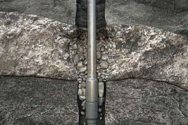
– This involves the physical obstruction of the drill pipe by wellbore instability, such as collapsed formations, hole enlargement (washouts), or the presence of cuttings and debris. Mechanical sticking is often associated with geomechanical issues like borehole collapse or keyseating.
3. Pack-Off Sticking:
– Occurs when drilling cuttings or other debris accumulate around the drill string, preventing it from moving. This can be exacerbated by inadequate hole cleaning, low mud circulation rates, or poor drilling practices.
Geomechanical Factors Contributing to Stuck Pipe
1. Borehole Instability:
– Instability in the borehole, such as formation collapse, can lead to mechanical sticking. This is often caused by high in-situ stresses, inappropriate mud weight, or weak rock formations. In unstable formations, the wellbore may collapse around the drill string, trapping it in place.
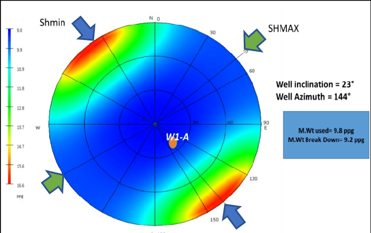
2. In-Situ Stress and Wellbore Orientation:
– The orientation of the wellbore relative to the in-situ stress field plays a critical role in stuck pipe incidents. For example, drilling in a direction that is not aligned with the minimum horizontal stress can lead to stress concentrations around the wellbore, increasing the likelihood of borehole collapse and mechanical sticking.
3. Mud Weight and Pressure Management:
– The choice of mud weight is crucial. If the mud weight is too low, it may not provide enough support to the wellbore, leading to collapse. Conversely, if it is too high, it can cause differential sticking by creating a large pressure difference between the wellbore and the formation.
4. Formation Properties:
– The mechanical properties of the formation, such as its compressive strength, porosity, and permeability, affect how it responds to drilling. Weak formations, such as shales, are more prone to collapse and may lead to stuck pipe situations.
5. Tectonic Activity:
– In regions with significant tectonic activity, the stress field may be highly variable, increasing the risk of wellbore instability and stuck pipe. Seismic events or ongoing tectonic deformation can alter the stress conditions in the subsurface, leading to unexpected borehole issues.
6. Wellbore Geometry:
– The design of the wellbore, including its trajectory and diameter, can influence the risk of stuck pipe. Complex well paths, such as those with high angles or long horizontal sections, are more prone to differential sticking and mechanical sticking due to the increased contact area between the drill string and the wellbore.
Assessment and Mitigation Techniques
1. Geomechanical Modeling:
– Geomechanical models can predict the stress distribution around the wellbore and identify potential zones of instability. By incorporating data on rock properties, in-situ stress, and wellbore geometry, these models help in planning the optimal drilling trajectory and mud weight to minimize the risk of stuck pipe.
2. Borehole Imaging and Logging:
– Tools like caliper logs, acoustic logs, and borehole imaging can detect wellbore instability features such as breakout zones, washouts, or keyseats. This real-time data helps in assessing the risk of stuck pipe and making informed decisions during drilling.
3. Real-Time Monitoring:
– Monitoring drilling parameters in real-time, such as torque, drag, and mud flow rates, can provide early warning signs of potential stuck pipe incidents. Sudden increases in torque or drag may indicate the onset of differential sticking or mechanical sticking.
4. Drilling Fluid Optimization:
– Optimizing drilling fluid properties, including its density, viscosity, and filtration characteristics, is essential for managing borehole pressure and ensuring effective hole cleaning. The correct mud weight should balance wellbore stability with the need to avoid differential sticking.
5. Casing and Liner Programs:
– Proper casing and liner placement can stabilize weak or unstable formations, reducing the risk of borehole collapse and stuck pipe. Casing programs should be designed based on geomechanical analysis to ensure the wellbore remains stable throughout the drilling process.
6. Directional Drilling Techniques:
– Careful planning of the wellbore trajectory to avoid high-stress zones or unstable formations can reduce the risk of stuck pipe. Directional drilling techniques, such as steering the wellbore away from fault zones or optimizing the drilling angle relative to the stress field, are important for managing geomechanical risks.
7. Mitigation Strategies:
– If stuck pipe occurs, various techniques can be employed to free the pipe, including jarring, back reaming, or applying chemical spotting fluids to reduce differential sticking. However, prevention through careful geomechanical assessment and planning is the most effective strategy.
Case Studies and Examples
– Shale Instability: In many regions, drilling through shales can lead to borehole instability due to their weak mechanical properties. A geomechanical analysis might reveal the need for increased mud weight or the use of inhibitive drilling fluids to stabilize the shale and prevent stuck pipe.
– Salt Formations: Drilling through salt formations can cause differential sticking due to the plasticity and creep behavior of salt. Geomechanical modeling helps in understanding the time-dependent behavior of salt and in designing appropriate mud weights and drilling practices to avoid stuck pipe.
Conclusion
Geomechanics plays a critical role in assessing and mitigating stuck pipe risks during drilling operations. By understanding the interaction between the wellbore, drilling parameters, and the surrounding rock, drilling engineers can design more effective well plans, select appropriate mud weights, and monitor drilling conditions in real-time to prevent stuck pipe incidents. This not only reduces the risk of costly delays and equipment damage but also ensures safer and more efficient drilling operations.
Geomechanics Well Trajectory Planning involves the integration of geomechanical principles into the design and execution of a wellbore’s path to optimize drilling performance, reduce risks, and ensure the stability of the well throughout its life cycle. Proper well trajectory planning is essential in complex geological settings, such as in high-pressure/high-temperature (HPHT) environments, deepwater drilling, or when drilling through unstable formations like shales or faulted zones.
Importance of Geomechanics in Well Trajectory Planning
1. Wellbore Stability:
– Understanding the stress field and rock mechanical properties along the planned trajectory helps prevent wellbore instability issues such as collapse, fracturing, or stuck pipe. Proper trajectory design minimizes these risks by avoiding high-stress zones or weak formations.
2. Minimizing Non-Productive Time (NPT):
– By anticipating and mitigating geomechanical risks, well trajectory planning can significantly reduce non-productive time associated with wellbore instability, stuck pipe, or other drilling complications.
3. Optimizing Drilling Efficiency:
– A well-designed trajectory that accounts for geomechanical conditions ensures smoother drilling operations, reducing the need for corrective actions such as reaming or sidetracking.
4. Reservoir Access and Completion:
– Geomechanical considerations help ensure that the wellbore effectively intersects the target reservoir with minimal damage to the formation, optimizing production and facilitating well completion.
Key Geomechanical Factors in Well Trajectory Planning
1. In-Situ Stress Field:
– The in-situ stress field (comprising vertical stress, minimum horizontal stress, and maximum horizontal stress) is a critical factor in well trajectory design. Understanding the orientation and magnitude of these stresses allows for optimizing the well path to minimize the risk of wellbore collapse, fracturing, or sanding.
2. Rock Mechanical Properties:
– The mechanical properties of the formations to be drilled, including compressive strength, tensile strength, Young’s modulus, and Poisson’s ratio, influence how the wellbore will respond to drilling. These properties help in selecting the optimal mud weight and drilling practices to maintain stability.
3. Formation Pressure:
– The pressure within the formation, or pore pressure, affects the risk of wellbore instability. High pore pressure zones require careful planning to avoid blowouts, differential sticking, or wellbore collapse.
4. Faults and Fractures:
– Existing faults and fractures can significantly impact wellbore stability. Drilling across or near these features requires special attention to avoid triggering seismic events, lost circulation, or wellbore instability.
5. Tectonic Settings:
– The regional tectonic setting influences the in-situ stress field and can lead to complex stress regimes. Understanding the tectonic environment is essential for planning a well trajectory that avoids unstable zones or areas of high stress concentration.
6. Mud Weight and Drilling Fluid Design:
– The choice of drilling fluid, particularly its density, directly impacts wellbore stability. The mud weight must be sufficient to counterbalance the formation pressure without fracturing the formation or causing differential sticking.
Steps in Geomechanical Well Trajectory Planning
1. Data Collection and Analysis:
– Gather all relevant geomechanical data, including well logs, core samples, seismic data, and regional stress field information. This data is used to create a geomechanical model that predicts how the formations will behave under drilling conditions.
2. Geomechanical Modeling:
– Develop a geomechanical model that simulates the stress distribution, pore pressure, and mechanical properties along the planned trajectory. This model helps in identifying potential risks and optimizing the well path.
3. Trajectory Design:
– Design the well trajectory considering the geomechanical model. Key decisions include the wellbore inclination and azimuth, the depth of critical casing points, and the avoidance of problematic zones such as high-stress areas or weak formations.
4. Mud Weight and Fluid Design:
– Based on the geomechanical model, select the appropriate mud weight and drilling fluid composition to maintain wellbore stability while minimizing the risk of formation damage or differential sticking.
5. Risk Assessment and Mitigation:
– Conduct a detailed risk assessment to identify potential geomechanical hazards, such as fault reactivation, wellbore collapse, or overpressure zones. Develop mitigation strategies, such as adjusting the well path, optimizing mud weight, or using specialized drilling techniques.
6. Real-Time Monitoring and Adjustment:
– During drilling, monitor key parameters such as torque, drag, mud pressure, and wellbore stability indicators in real-time. Use this data to adjust the well trajectory or drilling parameters as needed to address emerging geomechanical challenges.
Example Applications
1. Extended Reach Drilling (ERD):
– In ERD projects, the wellbore extends horizontally for long distances, increasing the risk of wellbore instability due to the high horizontal stress. Geomechanical well trajectory planning helps optimize the well path to manage stress distribution and prevent collapse or fracturing.
2. HPHT Environments:
– High-pressure, high-temperature environments present significant challenges for wellbore stability. Accurate geomechanical modeling and well trajectory planning are essential to manage the increased stress and pressure conditions, ensuring safe and effective drilling.
3. Unconventional Reservoirs:
– In unconventional reservoirs, such as shale gas plays, the wellbore often needs to be placed within specific, often thin, target zones. Geomechanical considerations are crucial to maintain wellbore stability and avoid mechanical failures during drilling.
4. Faulted and Fractured Reservoirs:
– When drilling in reservoirs with known faults or natural fractures, well trajectory planning must account for the potential for fault reactivation or wellbore instability. This involves careful analysis of the stress regime and the mechanical properties of the rock.
Challenges in Geomechanics Well Trajectory Planning
1. Data Uncertainty:
– Geomechanical models rely on accurate input data, which can be uncertain or incomplete. This uncertainty must be managed through sensitivity analyses and conservative design choices.
2. Complex Geological Settings:
– In areas with complex geology, such as those with multiple fault systems or variable stress fields, trajectory planning becomes more challenging and may require advanced modeling techniques and real-time adjustments during drilling.
3. Balancing Competing Objectives:
– Well trajectory planning often involves trade-offs between different objectives, such as optimizing reservoir exposure, minimizing drilling costs, and managing geomechanical risks. Achieving the right balance requires careful planning and collaboration between geoscientists, engineers, and drillers.
Conclusion
Geomechanics well trajectory planning is a critical component of successful drilling operations, particularly in challenging environments. By integrating geomechanical models with drilling and completion strategies, operators can design well trajectories that optimize reservoir access while minimizing risks associated with wellbore instability, stuck pipe, and other geomechanical hazards. This approach not only improves drilling efficiency and safety but also enhances the long-term performance and integrity of the well.

Mud Weight and Losses Assessment is a crucial aspect of drilling operations that focuses on optimizing mud weight to maintain wellbore stability and prevent losses during drilling. The correct mud weight ensures that the wellbore remains stable, prevents influxes (kicks), and minimizes the risk of mud losses into the formation. Geomechanical analysis is essential in determining the optimal mud weight window, which balances these objectives.
Importance of Mud Weight in Drilling Operations
1. Wellbore Stability:
– The primary function of drilling mud is to stabilize the wellbore by exerting pressure against the formation walls. An optimal mud weight prevents the collapse of the wellbore in unstable formations.
2. Preventing Kicks:
– If the mud weight is too low, it may not adequately counterbalance the formation pressure, leading to an influx of formation fluids into the wellbore, known as a kick. Severe kicks can escalate into blowouts, which are dangerous and costly.
3. Avoiding Lost Circulation:
– Conversely, if the mud weight is too high, it can fracture the formation, leading to lost circulation, where drilling mud flows into the formation rather than returning to the surface. This not only increases costs but can also lead to well control issues.
4. Minimizing Formation Damage:
– Excessively high mud weight can cause damage to the formation, particularly in reservoirs, by pushing mud into the pores of the rock, reducing permeability and potentially harming hydrocarbon production.
Geomechanical Factors Influencing Mud Weight
1. In-Situ Stress:
– The in-situ stress field, including the vertical stress, minimum horizontal stress, and maximum horizontal stress, determines the safe mud weight window. The mud weight must be sufficient to support the wellbore against collapse (governed by the minimum horizontal stress) but not so high that it induces fracturing (governed by the minimum horizontal stress).
2. Pore Pressure:
– Pore pressure is the pressure within the formation’s pore spaces. The mud weight needs to be higher than the pore pressure to prevent formation fluid influx but lower than the fracture pressure to avoid lost circulation.
3. Formation Strength:
– The strength of the formation rock, including its compressive strength and tensile strength, influences the risk of wellbore collapse or fracturing. Weaker formations require more careful mud weight management.
4. Formation Permeability:
– Highly permeable formations are more prone to differential sticking if the mud weight is too high. These formations can also be more susceptible to lost circulation if fractures are induced.
5. Tectonic Setting:
– In tectonically active areas, the stress regime can be highly variable, leading to challenges in maintaining an appropriate mud weight. For example, strike-slip or thrust fault regimes might have higher horizontal stresses, requiring a different approach than in normal fault regimes.
Mud Weight Window
The mud weight window is the range between the minimum mud weight required to prevent wellbore collapse (lower bound) and the maximum mud weight that can be applied without fracturing the formation (upper bound). The safe mud weight window is calculated based on:
1. Collapse Pressure (Lower Bound):
– This is the pressure required to prevent the wellbore from collapsing, which is influenced by the minimum horizontal stress and the rock strength.
2. Fracture Pressure (Upper Bound):
– This is the pressure at which the formation will fracture, often approximated using the minimum horizontal stress and the tensile strength of the rock.
Geomechanical Analysis for Mud Weight Optimization
1. Data Collection:
– Gather data on formation pressures, rock mechanical properties, and stress field information. This can include well logs, core samples, seismic data, and offset well information.
2. Geomechanical Modeling:
– Develop a geomechanical model to simulate the stress distribution around the wellbore. The model helps in predicting the collapse pressure and fracture pressure at various depths, providing a detailed mud weight window.
3. Pore Pressure Prediction:
– Accurate prediction of pore pressure is essential. Techniques such as Eaton’s method, D-exponent method, and sonic log analysis are commonly used to estimate pore pressure from drilling data.
4. Fracture Gradient Estimation:
– The fracture gradient can be estimated using empirical correlations or by analyzing leak-off tests (LOTs) and formation integrity tests (FITs). The fracture gradient defines the upper limit of the mud weight window.
5. Sensitivity Analysis:
– Perform sensitivity analysis to assess how variations in input parameters, such as changes in pore pressure or rock strength, affect the mud weight window. This helps in understanding the robustness of the chosen mud weight.
6. Real-Time Monitoring and Adjustment:
– During drilling, monitor parameters such as torque, drag, and mud flow rates in real-time. Sudden changes may indicate that the mud weight is outside the safe window, requiring adjustments to prevent instability or losses.
Managing Mud Losses
1. Identifying Loss Zones:
– Losses often occur in naturally fractured formations, highly permeable zones, or when drilling through weak formations. Identifying these zones early is critical for preventing losses.
2. Loss Circulation Materials (LCMs):
– When losses are detected, loss circulation materials can be added to the mud to seal off fractures or permeable zones, reducing further losses. LCMs can include fibrous materials, flakes, or other particulates designed to bridge and seal openings.
3. Mud Weight Adjustment:
– If losses are persistent, reducing the mud weight may help mitigate the issue. However, this must be done carefully to avoid falling below the collapse pressure, which could lead to wellbore instability.
4. Casing and Zonal Isolation:
– In some cases, running casing or liners to isolate weak or loss-prone zones can help stabilize the wellbore and prevent losses. Casing points should be selected based on geomechanical analysis to ensure they are placed in stable zones.
5. Drilling Fluid Selection:
– The type of drilling fluid used can influence the likelihood of mud losses. For example, oil-based muds may be more suitable in some formations due to their lower risk of inducing formation fractures compared to water-based muds.
Example Applications
1. HPHT Wells:
– In high-pressure/high-temperature wells, the margin between pore pressure and fracture pressure is often very narrow. Geomechanical modeling is critical to defining the safe mud weight window and avoiding both kicks and losses.
2. Unconventional Reservoirs:
– In unconventional plays like shale gas, maintaining wellbore stability while avoiding formation damage is challenging. Optimizing mud weight to manage these competing risks is essential for successful drilling and production.
3. Deepwater Drilling:
– Deepwater environments present unique challenges, including narrow mud weight windows and complex pressure regimes. Geomechanical analysis is crucial for safely managing these conditions.
Conclusion
Mud weight and losses assessment is a fundamental part of well planning and drilling operations. By integrating geomechanical models, real-time monitoring, and careful planning, operators can optimize mud weight to maintain wellbore stability, prevent kicks, and minimize the risk of mud losses. This not only enhances drilling efficiency but also ensures the safety and success of the entire drilling operation.
The mission of Syntillica is to provide the best quality consulting support to the Energy Industry.