


Hydrocarbon production chemistry focuses on the extraction, refining, and processing of hydrocarbons to produce fuels, chemicals, and materials. Hydrocarbons, primarily found in crude oil and natural gas, are the backbone of the petrochemical industry. The field involves various processes and technologies to convert raw hydrocarbons into usable products efficiently and sustainably.
Key Components and Processes in Hydrocarbon Production Chemistry
1. Exploration and Extraction
2. Separation and Treatment
3. Refining Processes
4. Chemical Processing
6. Environmental and Safety Considerations
7. Economic and Sustainability Aspects
Applications
Advanced Technologies in Hydrocarbon Production
Hydrocarbon production chemistry is a dynamic and critical field that supports the global energy supply and the production of a wide range of essential chemicals and materials.
There isn't enough time to list everything that we do so if you can't find what you are looking for from the Services menu please contact the team and we'll be happy to respond to your request.
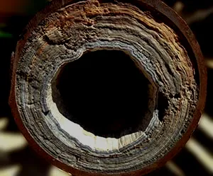
Scaling in pipelines is a significant issue in the oil and gas industry and in other sectors involving fluid transport, such as water treatment and chemical processing. Scaling refers to the deposition of mineral solids from fluids onto the inner surfaces of pipelines and other equipment. This can lead to reduced flow capacity, increased pressure drops, and even complete blockages, which can cause operational inefficiencies, increased maintenance costs, and potential safety hazards.
Causes of Scaling
Scaling typically occurs when the fluid’s conditions change, leading to the precipitation of dissolved minerals. Key factors contributing to scaling include:
1. Temperature Changes: Higher temperatures can reduce the solubility of certain minerals, causing them to precipitate.
2. Pressure Changes: Reductions in pressure can lead to the release of gases or changes in the solubility of minerals.
3. Chemical Composition: High concentrations of scaling ions like calcium (Ca²⁺), magnesium (Mg²⁺), bicarbonate (HCO₃⁻), sulfate (SO₄²⁻), and carbonate (CO₃²⁻).
4. pH Levels: Changes in pH can shift the equilibrium of dissolved species, leading to precipitation.
5. Supersaturation: When the concentration of scaling minerals exceeds their solubility limit.
Common Types of Scale
1. Calcium Carbonate (CaCO₃): Commonly forms in water systems with high bicarbonate and calcium ion concentrations, especially at higher pH and temperatures.
2. Calcium Sulfate (CaSO₄): Can form in systems with high sulfate and calcium concentrations, typically influenced by temperature and pressure.
3. Barium Sulfate (BaSO₄): Precipitates in the presence of barium and sulfate ions, often difficult to remove.
4. Strontium Sulfate (SrSO₄): Similar to barium sulfate but involves strontium ions.
5. Silica (SiO₂): Forms under high-temperature and high-pH conditions, often in geothermal and industrial water systems.
Prevention and Mitigation Strategies
1. Chemical Inhibition: Adding scale inhibitors to the fluid, which interfere with the crystallization process of scale-forming minerals.
– Phosphonates: Effective at low concentrations, commonly used in oilfield applications.
– Polyacrylates: Used in water treatment and industrial applications.
2. pH Control: Adjusting the pH of the fluid to keep scale-forming ions in solution.
3. Softening: Removing hardness ions (calcium and magnesium) through ion exchange or precipitation methods.
4. Descaling Agents: Using acids or chelating agents to dissolve existing scale deposits.
5. Mechanical Cleaning: Pigging, scraping, or hydro-jetting to physically remove scale deposits.
6. Electromagnetic and Ultrasonic Devices: Using electromagnetic fields or ultrasonic waves to alter the crystallization process and prevent scale formation.
Monitoring and Detection
1. Regular Inspections: Using inline inspection tools (smart pigs) to detect and measure scale deposits.
2. Flow and Pressure Monitoring: Monitoring changes in flow rates and pressure drops to identify potential scaling issues.
3. Chemical Analysis: Regularly analyzing the chemical composition of the fluid to predict and manage scaling risks.
4. Visual Inspections: Using boroscopes or other visual inspection tools to observe the internal condition of pipelines.
Case Study Example
In the oil and gas industry, a common scenario involves the production of oil with high water content (produced water), which often contains high levels of calcium and bicarbonate ions. As the produced water is brought to the surface, pressure and temperature changes can lead to the precipitation of calcium carbonate scale. This can be mitigated by injecting scale inhibitors downhole to prevent scale formation before the water reaches the surface facilities.
Conclusion
Effective management of scaling in pipelines requires a combination of predictive monitoring, chemical treatment, and mechanical intervention. Understanding the specific conditions and chemistry of the fluid system is essential for developing tailored solutions to prevent and mitigate scaling issues, ensuring the smooth and efficient operation of pipeline systems.
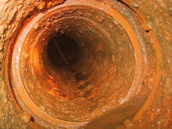
Hydrocarbon pipeline corrosion is a critical issue in the oil and gas industry, as it can lead to pipeline failures, environmental contamination, and significant economic losses. Corrosion in hydrocarbon pipelines can occur due to a variety of factors, including the presence of water, oxygen, carbon dioxide (CO₂), hydrogen sulfide (H₂S), and certain bacteria. Understanding the mechanisms of corrosion and implementing effective prevention and mitigation strategies are essential for maintaining pipeline integrity and safety.
Types of Corrosion in Hydrocarbon Pipelines
1. Uniform Corrosion:
– Mechanism: Occurs uniformly across the surface of the pipeline material.
– Cause: General exposure to corrosive environments such as water and CO₂.
– Impact: Gradual thinning of the pipeline wall, leading to potential leaks or ruptures.
2. Pitting Corrosion:
– Mechanism: Localized corrosion resulting in small pits or holes.
– Cause: Presence of chloride ions or other aggressive species.
– Impact: Can cause rapid failure due to localized penetration of the pipeline wall.
3. Galvanic Corrosion:
– Mechanism: Occurs when two different metals are electrically connected in a corrosive electrolyte.
– Cause: Contact between dissimilar metals, such as steel and copper.
– Impact: The more anodic metal corrodes preferentially, potentially leading to significant damage.
4. Stress Corrosion Cracking (SCC):
– Mechanism: Crack initiation and propagation due to the combined effect of tensile stress and a corrosive environment.
– Cause: High-stress conditions and the presence of corrosive agents like H₂S.
– Impact: Can lead to sudden and catastrophic pipeline failure.
5. Microbiologically Influenced Corrosion (MIC):
– Mechanism: Corrosion caused by the activity of microorganisms, such as sulfate-reducing bacteria (SRB).
– Cause: Biofilms and microbial activity in the presence of water and nutrients.
– Impact: Accelerated corrosion rates and localized pitting.
6. Erosion Corrosion:
– Mechanism: Accelerated corrosion due to the relative movement of a corrosive fluid against the pipeline surface.
– Cause: High-velocity flow, sand particles, or other abrasive materials in the fluid.
– Impact: Rapid material loss and potential pipeline failure.
Prevention and Mitigation Strategies
1. Material Selection:
– Corrosion-resistant Alloys: Using materials like stainless steel or corrosion-resistant alloys (CRAs) for pipeline construction.
– Coatings and Linings: Applying protective coatings or linings to the pipeline interior and exterior surfaces.
2. Cathodic Protection:
– Impressed Current Systems: Using an external power source to provide a continuous flow of electrical current to the pipeline, preventing anodic reactions.
– Sacrificial Anode Systems: Attaching sacrificial anodes made of more anodic materials (e.g., zinc, magnesium) to protect the pipeline.
3. Chemical Inhibition:
– Corrosion Inhibitors: Injecting chemicals that form a protective film on the pipeline surface to prevent corrosive reactions.
– Biocides: Using biocides to control microbial activity and prevent MIC.
4. Pipeline Design and Operation:
– Flow Rate Control: Managing flow rates to minimize erosion corrosion.
– Separation and Dehydration: Removing water and other corrosive agents from hydrocarbons before transportation.
– Pipeline Pigging: Regular cleaning of pipelines using pigs to remove deposits and prevent corrosion.
5. Monitoring and Inspection:
– Corrosion Monitoring Devices: Installing corrosion probes and sensors to continuously monitor corrosion rates.
– Inline Inspection Tools: Using smart pigs and other inspection tools to detect corrosion and assess pipeline integrity.
– Regular Maintenance: Conducting scheduled inspections and maintenance to identify and address corrosion issues early.
Case Study Example
A common scenario in the oil and gas industry is the presence of CO₂ and H₂S in natural gas, which can lead to corrosion in carbon steel pipelines. To mitigate this, operators may use corrosion-resistant alloys or apply internal coatings. Additionally, they might implement cathodic protection systems and regularly inject corrosion inhibitors into the gas stream. Regular monitoring using smart pigs and corrosion probes ensures early detection of corrosion, allowing for timely maintenance and repair.
Conclusion
Effective management of hydrocarbon pipeline corrosion requires a comprehensive approach that includes material selection, protective coatings, cathodic protection, chemical inhibition, and regular monitoring and maintenance. By understanding the specific conditions and challenges associated with pipeline corrosion, operators can implement strategies to enhance pipeline longevity, safety, and reliability.

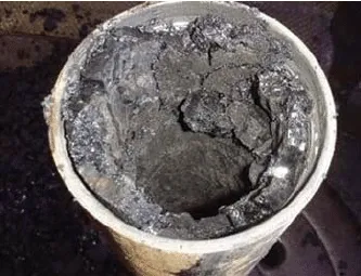
Waxy crude oil, often referred to as paraffinic crude oil, contains a significant amount of paraffin wax. These waxes are solid hydrocarbons that can precipitate out of the oil when the temperature drops below the wax appearance temperature (WAT). Managing waxy crude oil poses unique challenges in the oil and gas industry, particularly in terms of flow assurance, transportation, and production.
Characteristics of Waxy Crude Oil
1. High Wax Content: Waxy crude oils contain a substantial amount of paraffin wax, which can crystallize and form deposits at lower temperatures.
2. High Pour Point: The temperature at which the oil ceases to flow easily is known as the pour point. Waxy crudes generally have a high pour point.
3. Wax Appearance Temperature (WAT): The temperature at which wax crystals start to form. Below this temperature, wax precipitation begins.
Challenges Associated with Waxy Crude Oil
1. Flow Assurance:
– Wax deposition in pipelines can restrict flow, increase pressure drop, and even cause blockages.
– In subsea pipelines, where temperatures are naturally low, the risk of wax deposition is significant.
2. Transportation:
– Waxy oils can solidify during transport, necessitating heating systems or insulation for pipelines and storage tanks.
3. Production:
– Wax can accumulate on downhole equipment, including tubing and pumps, impairing production efficiency.
Prevention and Mitigation Strategies
1. Thermal Methods
– Insulation: Using insulated pipelines to maintain the temperature above the WAT.
– Heating: Installing heating systems (e.g., electrical heating, hot oil circulation) to keep the crude oil above the WAT during transport and storage.
2. Chemical Inhibition
– Pour Point Depressants (PPDs): Adding chemicals that modify wax crystal formation and lower the pour point.
– Wax Inhibitors: Chemicals that prevent wax crystals from agglomerating and depositing on pipeline walls.
– Dispersants: Chemicals that disperse wax particles in the oil, preventing them from settling and forming deposits.
3. Mechanical Methods
– Pigging: Regularly using pipeline pigs to clean and remove wax deposits from the pipeline interior.
– Scrapers: Installing scrapers to mechanically remove wax buildup in pipelines and equipment.
4. Operational Practices
– Temperature Control: Maintaining higher operational temperatures to keep the oil above the WAT.
– Flow Rate Management: Adjusting flow rates to minimize wax deposition. Higher flow rates can help keep wax particles in suspension.
Monitoring and Detection
1. Temperature and Pressure Monitoring: Continuously monitoring temperatures and pressures to detect conditions favorable for wax deposition.
2. Inline Inspection Tools: Using smart pigs and other inline inspection tools to detect wax deposits and assess the condition of the pipeline.
3. Sampling and Analysis: Regularly sampling and analyzing the oil to monitor wax content and composition.
Case Study Example
In offshore oil production, waxy crude oil poses significant flow assurance challenges. To manage this, operators might:
1. Use insulated flowlines and risers to maintain the temperature of the crude oil above its WAT.
2. Inject pour point depressants or wax inhibitors continuously to prevent wax deposition.
3. Implement a regular pigging schedule to clean the pipelines and remove any wax buildup.
4. Use subsea heating systems, such as electric trace heating, to ensure the oil remains fluid during transport to the processing facility.
Conclusion
Managing waxy crude oil requires a multifaceted approach combining thermal, chemical, mechanical, and operational strategies. Understanding the specific properties of the waxy crude and the environmental conditions in which it is produced and transported is essential for developing effective prevention and mitigation techniques. Through careful monitoring and the implementation of appropriate strategies, the challenges associated with waxy crude oil can be effectively managed to ensure continuous and efficient production and transportation.

Hydrocarbon gas hydrates, commonly referred to as gas clathrates or simply hydrates, are crystalline compounds where gas molecules, typically methane, ethane, or propane, are trapped within a lattice of water molecules. These hydrates are stable at high pressures and low temperatures, conditions often found in deep-sea environments and permafrost regions.
Characteristics of Gas Hydrates
1. Structure: Gas hydrates have a crystalline structure where water molecules form a cage-like lattice around gas molecules.
2. Composition: Methane is the most common gas found in hydrates, but other hydrocarbons and gases like ethane, propane, butane, and even carbon dioxide can form hydrates.
3. Conditions for Formation: High pressure and low temperature are essential for hydrate formation. These conditions are prevalent in deepwater sediments and cold arctic regions.
Challenges Posed by Gas Hydrates
1. Flow Assurance: In oil and gas production, gas hydrates can form in pipelines and wellbores, leading to blockages and significant flow assurance problems.
2. Safety Hazards: Hydrate blockages can cause pressure build-up, potentially leading to pipeline rupture or blowouts.
3. Operational Issues: Managing hydrate formation requires additional operational procedures and equipment, increasing complexity and costs.
Prevention and Mitigation Strategies
1. Thermal Management
– Insulation: Insulating pipelines to maintain temperatures above hydrate formation conditions.
– Heating: Using electrical heating cables or circulating hot fluids to keep the temperature above the hydrate stability zone.
2. Pressure Management
– Depressurization: Reducing pressure in pipelines to move outside the hydrate stability zone. However, this is not always feasible in deepwater operations.
3. Chemical Inhibition
– Thermodynamic Inhibitors: Adding chemicals such as methanol or monoethylene glycol (MEG) to shift the hydrate formation conditions to lower temperatures and higher pressures.
– Kinetic Inhibitors: Using polymers that delay hydrate nucleation and growth, allowing more time for the fluid to be transported without forming hydrates.
– Anti-Agglomerants: Chemicals that prevent hydrate particles from sticking together, ensuring they remain dispersed in the flow.
4. Mechanical Methods
– Pigging: Regularly running pipeline pigs to remove water and hydrate precursors from pipelines.
– Hydrate Remediation Tools: Using mechanical devices to break up hydrate plugs if they form.
Monitoring and Detection
1. Temperature and Pressure Sensors: Continuous monitoring to ensure conditions remain outside the hydrate stability zone.
2. Inline Inspection Tools: Tools that can detect hydrate formation and measure pipeline conditions.
3. Flow Assurance Modeling: Predictive models to anticipate hydrate formation and plan mitigation strategies accordingly.
Applications and Research
1. Energy Resource Potential
Gas hydrates are considered a potential future energy resource due to the vast quantities of methane they contain. However, commercial exploitation is challenging due to technical and environmental concerns.
2. Environmental Impact
Methane is a potent greenhouse gas, and the release of methane from destabilized hydrates could contribute to climate change. Research is ongoing to understand the implications and develop safe extraction methods.
3. Advances in Technology
– Hydrate Inhibition Research: Development of more effective and environmentally friendly inhibitors.
– Hydrate Extraction Techniques: Innovative methods like depressurization, thermal stimulation, and chemical injection for safe methane extraction from hydrates.
Case Study Example
In deepwater drilling operations, managing gas hydrates is critical. For example, in the Gulf of Mexico, operators might:
1. Use insulated and heated risers to maintain the temperature of the produced fluids above the hydrate formation temperature.
2. Inject MEG continuously at the wellhead to inhibit hydrate formation as the gas ascends through the colder water column.
3. Conduct regular pigging operations to remove any water and hydrate precursors from the flowlines.
4. Deploy real-time monitoring systems to track temperature and pressure, ensuring they remain within safe operating limits.
Conclusion
Managing hydrocarbon gas hydrates is essential for ensuring the safe and efficient operation of oil and gas production systems, particularly in deepwater and arctic environments. A comprehensive approach that includes thermal management, chemical inhibition, mechanical methods, and continuous monitoring is crucial for preventing and mitigating hydrate-related issues. Ongoing research and technological advancements are vital for improving hydrate management strategies and exploring the potential of gas hydrates as a future energy resource.
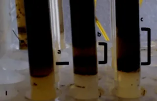
Asphaltenes are a complex mixture of high-molecular-weight, polycyclic aromatic hydrocarbons found in crude oil. They are insoluble in light alkanes like n-pentane or n-heptane but soluble in aromatic solvents such as toluene. Asphaltenes can precipitate out of crude oil under certain conditions, leading to significant challenges in oil production, transportation, and refining.
Characteristics of Asphaltenes
1. Complex Molecular Structure: Asphaltenes are large, complex molecules with a structure consisting of fused aromatic rings, heteroatoms (such as sulfur, nitrogen, and oxygen), and alkyl side chains.
2. Solubility: Insoluble in light alkanes (e.g., n-pentane, n-heptane) but soluble in aromatic solvents (e.g., toluene, benzene).
3. Stability: The stability of asphaltenes in crude oil depends on the oil’s composition and conditions such as temperature, pressure, and the presence of other chemicals.
Challenges Associated with Asphaltenes
1. Deposition: Asphaltenes can precipitate and deposit in pipelines, wellbores, and production facilities, leading to blockages and reduced flow efficiency.
2. Emulsions: Asphaltenes can stabilize water-in-oil emulsions, making oil-water separation difficult and increasing the cost of crude oil processing.
3. Refining Issues: High asphaltene content in crude oil can cause problems in refining processes, such as catalyst deactivation and fouling of equipment.
Factors Influencing Asphaltene Precipitation
1. Pressure and Temperature: Changes in pressure and temperature can destabilize asphaltenes, causing them to precipitate out of the oil.
2. Composition of Oil: The presence of light alkanes can induce asphaltene precipitation, while aromatic compounds help to keep them dissolved.
3. Chemical Additives: The use of certain chemicals can either stabilize or destabilize asphaltenes in crude oil.
Prevention and Mitigation Strategies
1. Chemical Inhibition
– Asphaltene Inhibitors: Chemicals that prevent asphaltene precipitation by stabilizing them in the crude oil.
– Dispersants: Chemicals that disperse precipitated asphaltene particles, preventing them from agglomerating and forming deposits.
2. Solvent Treatment
– Solvents: Injecting aromatic solvents (e.g., toluene, xylene) to dissolve asphaltenes and clean up deposits.
– Co-Solvents: Using co-solvents that enhance the solubility of asphaltenes and prevent their precipitation.
3. Operational Practices
– Pressure Management: Avoiding rapid pressure drops that can induce asphaltene precipitation.
– Temperature Control: Maintaining stable temperatures to prevent conditions that favor asphaltene deposition.
– Flow Assurance: Regular pigging and cleaning of pipelines to remove asphaltene deposits and maintain flow efficiency.
4. Monitoring and Detection
– Inline Monitoring: Using sensors to detect asphaltene precipitation and deposition in real-time.
– Sampling and Analysis: Regularly sampling crude oil and analyzing its composition to predict and manage asphaltene-related issues.
Case Study Example
In an offshore oil production scenario, operators may encounter asphaltene-related issues as follows:
1. Prevention: Continuously injecting asphaltene inhibitors into the production stream to stabilize asphaltenes.
2. Monitoring: Implementing real-time monitoring systems to track changes in pressure and temperature, ensuring they remain within safe operating limits.
3. Mitigation: Using pigging operations to mechanically remove any asphaltene deposits that form in the pipelines.
Advances in Technology and Research
1. Advanced Inhibitors and Dispersants: Development of more effective and environmentally friendly chemicals to prevent and mitigate asphaltene issues.
2. Predictive Modeling: Improved models to predict asphaltene behavior under different operational conditions, aiding in the design of effective prevention strategies.
3. Nano-technology: Utilizing nanomaterials to interact with asphaltenes and prevent their aggregation and deposition.
Conclusion
Managing asphaltenes in hydrocarbon production is critical for maintaining efficient and safe operations. A combination of chemical inhibition, solvent treatment, operational practices, and continuous monitoring is essential for preventing and mitigating asphaltene-related problems. Advances in technology and research are crucial for developing more effective solutions and improving our understanding of asphaltene behavior in crude oil systems.
Hydrocarbon emulsions, particularly water-in-oil emulsions, are a significant challenge in the oil and gas industry. These emulsions occur when water droplets become dispersed in crude oil, stabilized by natural surfactants such as asphaltenes and resins. Managing emulsions is crucial for efficient oil production, transportation, and refining.
Characteristics of Hydrocarbon Emulsions
1. Types of Emulsions:
– Water-in-Oil (W/O): Water droplets dispersed in oil. This is the most common type of emulsion in the oil industry.
– Oil-in-Water (O/W): Oil droplets dispersed in water, less common in upstream processes but can occur in downstream processing.
2. Stabilizers: Natural surfactants like asphaltenes, resins, waxes, and fine solids that stabilize emulsions by forming a film around the water droplets.
3. Droplet Size: Emulsion stability is influenced by the size of the water droplets; smaller droplets lead to more stable emulsions.
Challenges Associated with Hydrocarbon Emulsions
1. Production Issues: Emulsions can increase viscosity, making the oil harder to pump and process.
2. Separation Difficulties: Water-in-oil emulsions complicate the separation of water from crude oil, which is essential before refining.
3. Corrosion: Water in emulsions can lead to corrosion in pipelines and equipment.
4. Transport and Processing: Emulsions can cause issues in transportation and processing, increasing operational costs.
Formation Mechanisms
1. Shear Forces: High shear forces during pumping and flow through valves can create emulsions.
2. Natural Surfactants: Asphaltenes, resins, and other natural surfactants in crude oil stabilize emulsions.
3. Mixing: Mixing of oil and water phases during production and transport.
Prevention and Mitigation Strategies
1. Chemical Treatment
– Emulsifiers: Chemicals added to break emulsions by destabilizing the water-oil interface. These can be non-ionic, cationic, or anionic surfactants.
– Dehydrators: Chemical agents that help in the coalescence of water droplets, making them easier to separate from the oil phase.
2. Mechanical Methods
– Gravity Settlers: Vessels where the emulsion is allowed to settle, and water droplets coalesce and separate due to gravity.
– Centrifuges: Equipment that uses centrifugal force to enhance the separation of water from oil.
– Electrostatic Treaters: Devices that use an electric field to coalesce water droplets, facilitating separation.
3. Thermal Methods
– Heating: Reducing the viscosity of oil and promoting the coalescence of water droplets by heating the emulsion.
4. Operational Practices
– Flow Management: Reducing shear forces by managing flow rates and avoiding turbulent flow conditions.
– Regular Maintenance: Ensuring equipment and pipelines are clean to prevent the accumulation of stabilizing agents like asphaltenes.
Monitoring and Detection
1. Inline Sensors: Monitoring devices that measure the water content and droplet size distribution in the crude oil stream.
2. Sampling and Analysis: Regular sampling and laboratory analysis to understand the characteristics of the emulsion and adjust treatment strategies accordingly.
3. Real-Time Monitoring: Implementing real-time monitoring systems to detect changes in emulsion properties and adjust processes on-the-fly.
Case Study Example
In an offshore oil production scenario, managing emulsions is critical to ensure efficient processing:
1. Chemical Injection: Continuously injecting demulsifiers at the wellhead to prevent emulsion formation during production.
2. Heated Treaters: Using heated separators to reduce the viscosity of the oil and enhance the separation of water.
3. Electrostatic Coalescers: Installing electrostatic coalescers downstream to further separate any remaining water droplets from the crude oil.
4. Monitoring: Implementing real-time monitoring systems to track the effectiveness of demulsification and adjust chemical dosages as needed.
Advances in Technology and Research
1. Advanced Demulsifiers: Developing more effective and environmentally friendly demulsifiers tailored to specific crude oil compositions.
2. Nanotechnology: Utilizing nanoparticles to enhance the coalescence of water droplets and improve separation efficiency.
3. Predictive Modeling: Improving models to predict emulsion behavior under various operational conditions, aiding in the design of effective treatment strategies.
4. Smart Sensors: Developing smart sensors for real-time, accurate monitoring of emulsion properties, enabling dynamic adjustments to treatment processes.
Conclusion
Managing hydrocarbon emulsions is crucial for the efficient and cost-effective production, transportation, and refining of crude oil. A combination of chemical, mechanical, thermal, and operational strategies, along with continuous monitoring and advancements in technology, can effectively prevent and mitigate the challenges posed by emulsions. Understanding the specific properties of the emulsion and the conditions under which it forms is essential for developing tailored solutions that ensure smooth and efficient oil production and processing.

Hydrocarbon microbiology studies the interactions between microorganisms and hydrocarbons, focusing on how microbes can degrade, transform, or produce hydrocarbons. This field has significant applications in bioremediation, oil recovery, and understanding the ecological impacts of hydrocarbons in the environment.
Key Concepts in Hydrocarbon Microbiology
1. Hydrocarbon-Degrading Microorganisms:
– Bacteria: Various bacteria, such as Pseudomonas, Bacillus, and Alcanivorax, are known for their ability to degrade hydrocarbons.
– Fungi: Certain fungi, including species of Aspergillus and Penicillium, can metabolize hydrocarbons.
– Archaea: Some archaea, especially those in extreme environments, can also participate in hydrocarbon degradation.
2. Mechanisms of Hydrocarbon Degradation:
– Aerobic Degradation: In the presence of oxygen, microorganisms use hydrocarbons as a carbon and energy source, breaking them down into CO₂ and water.
– Anaerobic Degradation: In oxygen-deprived environments, microbes use alternative electron acceptors such as nitrate, sulfate, or iron to degrade hydrocarbons.
3. Metabolic Pathways:
– Alkane Degradation: Involves enzymes like alkane hydroxylase, which introduce an oxygen atom to the hydrocarbon chain, making it more reactive and easier to break down.
– Aromatic Hydrocarbon Degradation: Involves ring-cleaving dioxygenases that open up the aromatic ring, leading to the formation of simpler compounds that can be further metabolized.
Applications of Hydrocarbon Microbiology
1. Bioremediation
– Oil Spill Cleanup: Utilizing hydrocarbon-degrading microbes to clean up oil spills in marine and terrestrial environments.
– Land Reclamation: Applying bioremediation techniques to treat contaminated soils, turning them into usable land.
2. Enhanced Oil Recovery
– Microbial Enhanced Oil Recovery (MEOR): Injecting specific microbes or nutrients into oil reservoirs to stimulate the growth of hydrocarbon-degrading bacteria, which can produce biosurfactants and biogases to enhance oil flow and recovery.
3. Environmental Monitoring and Assessment
– Microbial Indicators: Using changes in microbial community composition as indicators of hydrocarbon contamination in environments like soil and water.
– Bioassays: Developing bioassays based on microbial activity to assess the toxicity and biodegradability of hydrocarbons in different environments.
4. Waste Treatment
– Industrial Wastewater Treatment: Employing microbial consortia to degrade hydrocarbons in industrial wastewater, reducing pollution and environmental impact.
– Sewage Treatment: Using hydrocarbon-degrading microbes in sewage treatment plants to remove hydrocarbons from wastewater.
Challenges and Future Directions
1. Environmental Variability: Microbial activity and efficiency in hydrocarbon degradation can be affected by environmental factors such as temperature, pH, salinity, and nutrient availability.
2. Microbial Community Dynamics: Understanding the interactions within microbial communities and their collective impact on hydrocarbon degradation is complex but crucial for optimizing bioremediation efforts.
3. Genetic Engineering: Advancements in genetic engineering and synthetic biology could enhance the hydrocarbon-degrading capabilities of microbes, making bioremediation and MEOR more efficient.
4. Field Applications: Scaling up laboratory findings to field applications remains challenging. Site-specific conditions require tailored approaches and continuous monitoring to ensure effectiveness.
Case Study Example
Deepwater Horizon Oil Spill (2010):
– Context: The Deepwater Horizon oil spill in the Gulf of Mexico released millions of barrels of oil into the marine environment.
– Microbial Response: Native hydrocarbon-degrading bacteria, such as Alcanivorax and Cycloclasticus, rapidly proliferated in the spill area, contributing to the natural attenuation of the oil.
– Bioremediation Efforts: Biostimulation (adding nutrients) and bioaugmentation (adding specific microbes) were employed to enhance the degradation process. The microbial community dynamics and environmental conditions were closely monitored to optimize the bioremediation efforts.
Conclusion
Hydrocarbon microbiology plays a crucial role in managing and mitigating the environmental impacts of hydrocarbons. Through the understanding and application of microbial processes, significant advancements can be made in bioremediation, enhanced oil recovery, and environmental monitoring. The future of this field lies in integrating advanced microbial techniques with environmental engineering to develop sustainable and effective solutions for hydrocarbon contamination and utilization.

Sour gas is natural gas that contains significant amounts of hydrogen sulfide (H₂S). This compound is highly toxic, corrosive, and has a distinct rotten egg smell. The presence of H₂S in natural gas poses various challenges for production, transportation, and processing, but also provides opportunities for sulfur recovery and other industrial applications.
Characteristics of Sour Gas
1. Hydrogen Sulfide (H₂S) Content: Sour gas typically contains H₂S concentrations above 4 ppm. The higher the H₂S content, the more corrosive and toxic the gas.
2. Corrosiveness: H₂S is highly corrosive to metals, particularly in the presence of water, forming sulfuric acid, which can damage pipelines, storage tanks, and equipment.
3. Toxicity: H₂S is extremely toxic to humans and animals, even at low concentrations, posing significant health and safety risks.
Challenges Associated with Sour Gas
1. Health and Safety: H₂S is hazardous, requiring strict safety measures to protect workers and surrounding communities.
2. Corrosion: The corrosive nature of H₂S demands the use of specialized materials and coatings for pipelines and equipment.
3. Environmental Impact: Emissions of H₂S and sulfur compounds can have detrimental environmental effects, requiring stringent environmental controls.
4. Processing and Treatment: Sour gas must be treated to remove H₂S and other contaminants before it can be safely used or transported.
Sour Gas Treatment and Processing Methods
1. Amine Gas Treating (Sweetening)
– Process: Sour gas is contacted with an amine solution (e.g., monoethanolamine (MEA), diethanolamine (DEA)) that absorbs H₂S and CO₂. The rich amine solution is then regenerated by heating, releasing the absorbed gases and allowing the amine to be reused.
– Advantages: Effective for removing H₂S and CO₂, widely used in the industry.
– Challenges: Requires significant energy for regeneration and handling of large volumes of chemicals.
2. Claus Process (Sulfur Recovery)
– Process: Converts H₂S from the amine treatment into elemental sulfur. The process involves partial combustion of H₂S to form sulfur dioxide (SO₂), followed by a reaction between H₂S and SO₂ to produce sulfur.
– Advantages: Efficiently recovers sulfur, which can be sold as a valuable byproduct.
– Challenges: Requires precise control of reaction conditions and handling of byproducts.
3. Solid Scavengers
– Process: Uses solid materials (e.g., iron oxide, zinc oxide) to chemically react with and remove H₂S from the gas stream.
– Advantages: Simple operation, useful for small-scale applications.
– Challenges: Limited capacity and the need for frequent replacement of scavenger material.
4. Membrane Separation
– Process: Uses selective permeability of membranes to separate H₂S and CO₂ from natural gas.
– Advantages: Compact, energy-efficient, and suitable for offshore and remote locations.
– Challenges: Membrane fouling and the need for pre-treatment to protect membranes.
5. Oxidation Processes
– Process: Converts H₂S to sulfur or sulfate using chemical oxidants or catalytic processes.
– Advantages: Can achieve high levels of H₂S removal.
– Challenges: Requires handling of oxidizing agents and potential formation of unwanted byproducts.
Monitoring and Safety Measures
1. H₂S Detection: Installing continuous monitoring systems to detect H₂S levels in production facilities and pipelines.
2. Personal Protective Equipment (PPE): Providing workers with appropriate PPE, including gas masks and protective clothing.
3. Emergency Response Plans: Developing and training personnel in emergency response plans for H₂S leaks or exposures.
4. Corrosion Monitoring: Regular inspection and maintenance of equipment and pipelines to detect and mitigate corrosion.
Case Study Example
In a sour gas processing facility, the following steps might be implemented:
1. Amine Gas Treating: Sour gas is treated with an amine solution to remove H₂S and CO₂.
2. Claus Process: The removed H₂S is processed in a Claus plant to recover sulfur.
3. Sulfur Handling: The recovered sulfur is purified and sold as a byproduct.
4. Monitoring and Safety: Continuous H₂S monitoring systems are installed, and workers are equipped with PPE. Regular training and emergency drills are conducted to ensure safety.
Advances in Technology and Research
1. Advanced Membranes: Development of more robust and selective membranes for efficient gas separation.
2. Biological Treatment: Exploring the use of microbes for biodesulfurization, a potentially cost-effective and environmentally friendly method.
3. Integrated Processes: Combining multiple treatment technologies to enhance efficiency and reduce costs.
4. Smart Monitoring Systems: Implementing IoT and AI-based systems for real-time monitoring and predictive maintenance.
Conclusion
Managing sour gas is critical for ensuring the safety, efficiency, and environmental compliance of hydrocarbon production and processing. A combination of chemical, physical, and biological treatment methods, along with stringent monitoring and safety measures, is essential for effectively handling sour gas. Advances in technology and research continue to improve the efficiency and sustainability of sour gas treatment processes, helping the industry meet regulatory standards and reduce operational risks.
Syntillica can provide expertise in Sour Gas studies to understand the source of souring in a reservoir and to adopt field development strategies (e.g. sulphate removal in injection waters) to mitigate its impact.
The mission of Syntillica is to provide the best quality consulting support to the Energy Industry.